Hardware
Note
Hardware is only necessary for systems which require data acquisition capabilities. To use the software in a visualisation/analysis mode only, this section is likely irrelevant and can be skipped.
In its basic form, the software does not directly support any acquisition hardware. The hardware support and data acquisition are provided by Plugins. In this way, a wide variety of hardware devices can potentially be used with the software. Some plugins are included with the package which support the Transient Absorption Spectrometer Reference Design.
Supported Hardware Devices
As of version 1.0, the following hardware plugins are included which support the Transient Absorption Spectrometer Reference Design:
-
Thorlabs BBD201 DC Motor Controller and DDS600 translation stage (
thorlabs_apt). Similar Thorlabs devices which communicate using the APT protocol should be relatively easy to implement due to the support being provided by the thorlabs-apt-device python library.
-
Thorlabs MC2000B (
thorlabs_mc2000b). Supported by the thorlabs-mc2000b python library.
-
Andor Zyla sCMOS camera attached to a fixed spectrograph device (
zylafixed). Any Andor camera which uses the SDK3 should also work with little or no modifications through the andor3 python library.
-
TRS-Interface device designed specifically for this platform (
trsi). The interface is required for the real-time synchronisation of the laser, chopper and (optionally) delay position monitoring. The hardware design and firmware are hosted as a separate project documented here.
Alignment CameraAny consumer webcam type device. To view infrared laser spots, the IR filter will likely need to be removed from the camera.
Dummy Hardware Devices
The default Configuration will create a set of “dummy” hardware devices. These are useful for demonstrating and testing purposes, allowing more features of the application to be exhibited without requiring real hardware to be connected. Obviously, these dummy devices won’t be useful for actual data acquisition!
If you would like to disable the dummy hardware, using the application purely for data visualisation
purposes, disable the loading of the hardware modules by changing load = ["scope"] in the
Plugins section of the Configuration File. This will retain the Scope panel,
allowing the loading and display of previously saved spectra. Alternatively, or in addition, you may
wish to set init_hardware = false under in the [hardware] section.
Hardware Status Panel
A simple dialog showing the state of the connected hardware devices can be found under the
View→Hardware Status menu. If a device is not connected or powered up during the startup of the
software, it will display as Missing or Error. Clicking the corresponding Reset button
will trigger re-detection of the device and may get it operating without a full restart of the
software. Note that some modules may depend on others being present, for example an Acquisition
plugin may depend on a delay, chopper, detector, and interface device being present and
operating. If a device is not being initialised properly, check the log (View→Log) to see if any
errors or warnings are displayed.
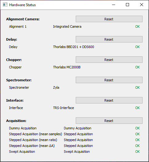
Hardware status panel showing all hardware plugins connected and ready to use.
Transient Absorption Spectrometer Reference Design
The layout and capabilities of the hardware for time-resolved data acquisition can vary widely. For the purposes of this documentation, discussion will be focussed on a reference design for a transient absorption spectrometer. This is a simple pump-probe apparatus as shown below.
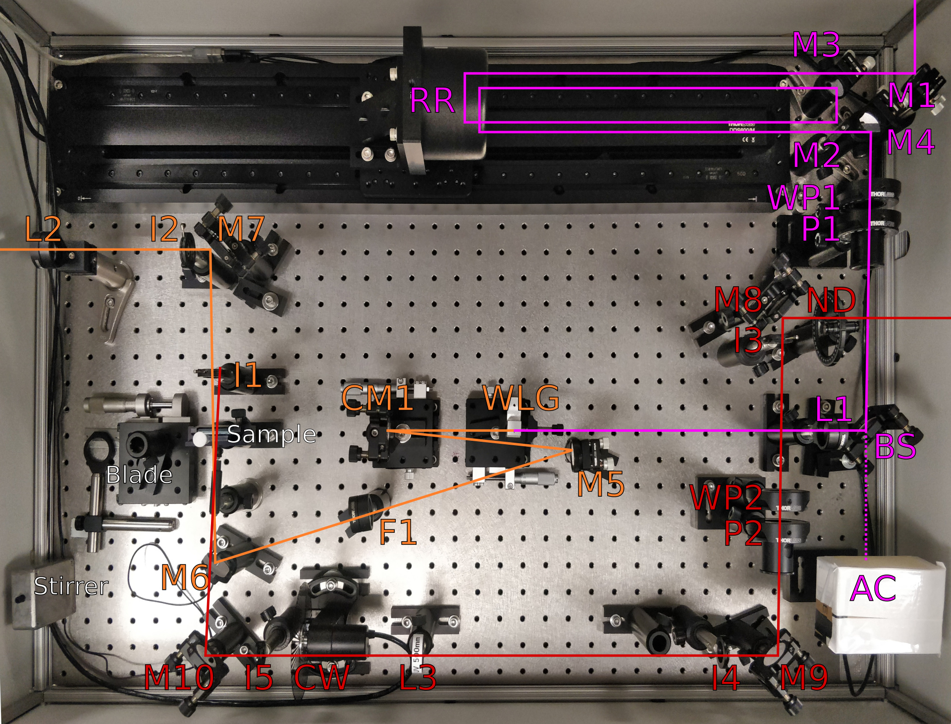
Overview of the reference design of the transient absorption spectrometer. The beam path for the seed used for white light continuum (probe) generation is indicated in magenta, the white light probe in orange, and the pump in red. M, mirror; RR, retroreflector; WP, λ/2 wave plate; P, polariser; BS, beamsplitter; AC, alignment camera; L, lens; WLG, white-light generation medium; CM, concave mirror; F, filter; I, iris; ND, neutral density filter; CW, chopper wheel.
Devices
Laser Source: Light Conversion Pharos PH2-SP-1mJ, a Ytterbium (Yb) 1030 nm laser with ~160 fs pulse duration. The laser is capable of repetition rates up to 10 kHz, but is usually run at 3.33 kHz or 5 kHz due to limitations in the detector capabilities.
Delay Stage: Thorlabs DDS600/M 600 mm translation stage with the Thorlabs BBD201 brushless DC motor controller. Similar controllers such as the BBD301 should be compatible with only minor changes to recognise the different USB device ID.
Optical Chopper Wheel: Thorlabs MC2000B optical chopper wheel with the MC1F60 chopper blade.
Detector: Andor Zyla 5.5 sCMOS camera attached to an Oriel spectrograph. The spectrograph range can be adjusted manually, but needs calibration parameters measured and entered into the
options = {}part of its configuration file.Interface: TRS-Interface, which is a custom microcontroller and circuitry to interface the synchronisation signals between the laser, chopper, and detector, and feed the chopper state and delay encoder counts to the host computer. The hardware designs and software are open source and may be modified to suit alternative devices if necessary.
Alignment Camera: A cheap USB webcam which has had its IR filter removed from behind its lens (there are many instructions and videos on the web about doing this modification). It is mounted inside a box which seals it off from ambient light, and is focussed on a cardboard screen.
White Light Continuum (Probe)
Approximately 5 µJ of the source laser is used as input to the spectrometer for probe generation. Only about 1–2 µJ is required to seed the white-light generation (WLG), but there are losses through the mirrors of the delay stage, plus some power is also split and sent to the alignment camera (AC).
The beam heights inside the spectrometer are nominally 132 mm, but this may be modified to match the input laser beam height and/or thickness of the breadboard the spectrometer is built upon.
The seed enters the spectrometer, hitting M1, which steers the beam into the hollow corner cube retroreflector (RR) of the delay. The beam enters the \((+x,+y)\) quadrant of RR, and exits the \((-x,-y)\) quadrant, hitting M2 then M3. M3 directs the beam back through the delay RR for a second pass, entering the \((+x,-y)\) quadrant and exiting the \((-x,+y)\) quadrant to hit M4. Note that during construction each pass through the delay should be aligned individually, which may require placing the alignment camera (AC) at the M2 position to isolate the effects of first pass.
M4 steers the beam from the delay section to the beamsplitter (BS). The λ/2 wave plate (WP1) and polariser (P1) combination are used to control the pulse energy of the seed and to set a vertical polarisation of the laser. BS splits the seed to feed a small amount to the alignment camera (AC), while steering the remainder through a lens (L1, \(f=300\) mm) on to the white-light generation medium (WLG). The WLG pictured is a 12 mm sapphire crystal. A sealed, 10-mm cuvette of D₂O (deuterium oxide, heavy water) has also been used as the WLG successfully. WLG is mounted on a micrometer translation stage to position it relative to the focus of L1 for optimum continuum generation. The white-light continuum is collected on the concave mirror (CM1, \(f=100\) mm) and directed to M5, keeping the angle of incidence and reflection as close to the normal as possible. CM1 is mounted on a micrometer stage to adjust the focus of the continuum at the sample position. M5 steers the continuum to M6 and M7, aiming for the target iris (I2), and passing through any required filters (F1, 1000 nm short-pass). The continuum is focussed on the sample (pictured is a 2-mm path length cuvette) and the iris I1. M7 steers the beam through the lens (L2, \(f=75\) mm) which focusses the signal on to the input slit of the detector (an Oriel spectrograph and Andor Zyla camera, not pictured).
Excitation Beam (Pump)
The pump is sourced from a suitable source such as a harmonic generation stage or optical parametric amplifier. The beam height is nominally 140 mm, which is slightly higher than that of the probe so that the pump and probe can cross with a minimal angle at the sample position.
The pump enters the spectrometer, hitting M8 and the target iris (I3). A neutral density filter (ND) can be used for adjustments of the pulse energy. M8 steers the beam to M9 and the target I4, passing through WP2 and P2 which are used for adjustment of the pulse energy and to set the desired polarisation (usually the magic angle, 54.7° relative to the probe). M9 steers the beam through the target I5 to M10. A lens (L3, \(f=500\) mm) adjusts the spot size at the sample position. The chopper wheel (CW) is placed so that the beam passes cleanly between its blades. M10 adjusts the aiming of the pump onto the sample and is used to optimise the pump and probe overlap. The residual pump beam should be blocked by I1.
Notes
The spectrometer is constructed on a 900x600 mm breadboard. A box with a lid is constructed around the breadboard, but is mounted to the optics table so that vibrations are not directly transmitted to the breadboard.
A razor blade attached to a micrometer stage is used for beam spot size measurements at the sample position.
A magnetic stirrer is used for solution samples, constructed from a magnet attached to a small hobby motor driven by a pulse-width modulated (PWM) speed controller.
Mirrors are protected silver. Retroreflector is protected gold, but silver may also be used.
WP1, P1, L1 should be suitable for the seed wavelength (1030 nm).
BS is a 70R/30T for NIR wavelengths, but the splitting ratio can be adjusted depending on input pulse energy etc.
WP2, P2, L3 should be suitable for the pump wavelengths used, typically in the visible range.
L2 should be suitable for the continuum wavelength generated, typically in the visible range.
Configuration File Sections
The [hardware] section of the Configuration File to run the reference hardware should
resemble something like below. The detector calibration parameters will need to be adjusted to match
the range of the spectrograph. Some additional options may be available for each section, see the
documentation for the respective plugin class for each device.
[hardware]

init_hardware = true
laser_reprate = 3333.333

[[hardware.aligncam]]
name = "Seed Alignment"
filter = ""
index = 0
focus = 49

[[hardware.delay]]
name = "Delay"
class = "Thorlabs_BBD201_DDS600"
options = { calibration_slope=-6.6711140760507e-16, calibration_offset=8.00533689126084e-09 }

[[hardware.chopper]]
name = "Chopper"
class = "Thorlabs_MC2000B"
options= {}

[[hardware.acquisition]]
name = "Stepped"
class = "TA_SteppedAcquisition"
options = {}

[[hardware.acquisition]]
name = "Swept"
class = "TA_SweptAcquisition"
options = { max_acquisitions = 100000 }

[[hardware.detector]]
name = "Spectrometer"
class = "ZylaFixed"
options = { calibration_coeffs = [486, 1.73637103e-01], flip_data = true }

[[hardware.interface]]
name = "Interface"
class = "TRSI"
options= {}